
Page 6 - Raritan Marine Elegance Owners Manual L490v0720v
P. 6
PLUMBING
PLUMBING
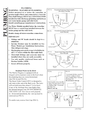
WARNING: HAZARD OF FLOODING FIG 3a Pressurized Freshwater Model Installed
Toilets mounted at or below the waterline, at Above/below Waterline
greatest angle of heel, and connected to a Seacock/
Thru Hull Fitting(s) MUST have VENTED LOOPS
installed in toilet discharge plumbing and between
raw water intake pump and toilet bowl. Discharge
Install vented loops per manufacturer’s instructions. Waterline Shut off Valve Holding Tank Waterline
Sea Water Models installed below the waterline Pressurized Fresh-
water
MUST have a vented loop installed between the Source
intake pump and the toilet bowl. FIG 3b Pressurized Freshwater Model Installed
Double clamp all below-waterline connections. below Waterline
IMPORTANT
• Fittings and 90° bends should be kept to a
minimum.
• In-Line Strainer may be installed on Sea Waterline Waterline
Water Models per Installation Instructions. Electroscan
This will prevent clogs. Discharge Seacock
• Discharging untreated sewage is forbidden in
all U. S. waters within the three-mile limit. FIG 3c Remote Intake Pump Model Mounted
below Waterline
• Thru-hull fittings and seacocks must be Discharge Vented Intake Vented Loop
Loop
installed where they are easily accessible.
• Use only quality reinforced hoses such as
Raritan Saniflex (SFH)
• Secure all hoses properly. Electroscan
remote pump
Discharge Intake Seacock
Seacock
Residual Water in the Bowl FIG 4a FIG 4b
The Marine Elegance is equipped with an
integral vent to maintain water in the bowl when Toilet installed below waterline
the plumbing lines are routed downward or below Treatment Device
and or holding Tank = Upward
(See FIG 4a and FIG 4b). discharge flow
The Smart Toilet Control (STC) is designed to Toilet Installed above waterline Do not remove vent cap
add water at the end of the flush cycle. The toilet or above Treatment Device and
will not hold more than about 4” in the bowl. or Holding Tank = Downward
If any of the discharge hose runs higher than discharge flow
Remove vent cap
the internal integral vent, DO NOT REMOVE
THE VENT CAP. For vent to work properly
in downward installation, the vent cap must be FIG 5
removed (see FIG 5).
Vent Cap
To enable vent, remove Vent Cap (FIG 5).
6 L490 0720jlc