
Page 4 - Raritan FreshHead Owners Manual L524-v1016
P. 4
Tools Required Additional Parts Required
INSTALLATION
• 5/16" nut driver to hose clamp • 1/2" NPT male adapter for inlet
• Wrench or screw driver • Four stainless steel mounting bolts or lag screws
• Bit for drilling mounting surface (minimum 5/16" [8mm]) and washers
• Hose cutters • 1 1/2" I.D. discharge hose
• Tape measure • 1/2" I.D. reinforced intake hose
• Hose clamps (two for each connection below waterline)
MOUNTING
Mounting surface must be flat and solid. Fig. 7
1. Mark location of toilet base mounting holes
on mounting surface.
2. Install seat on toilet.
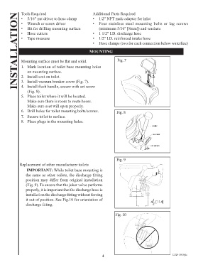
3. Install vacuum breaker cover (Fig. 7).
4. Install flush handle, secure with set screw
(Fig. 8).
5. Place toilet where it will be located.
Make sure there is room to route hoses.
Make sure seat will open properly.
6. Drill holes for toilet mounting bolts/screws. Fig. 8
7. Secure toilet to surface.
8. Place plugs in the mounting holes.
Fig. 9
Replacement of other manufacturer toilets
IMPORTANT: While toilet base mounting is
the same as other toilets, the discharge fitting
position may differ from original installation
(Fig. 9). To ensure that the joker valve performs
properly, it is important that the discharge hose is
installed on the discharge fitting without forcing
it out of position. See Fig.10 for orientation of
discharge fitting.
Fig. 10
4 L524 1016jlc
4