
Page 9 - Raritan Hold-N-Treat for Purasan EX L519v0919
P. 9
.
WIRING (See Fig 10) Optional position sensing shutoff valve,
WARNING: Hazard of Shock and Fire Position Monitored Ball Valve part# 90657:
• Always use proper wire, connectors and fuse/ 1. Run wires between valve and control module
circuit breaker. See Specification Chart. SPC as per wiring diagram WIRING
• Secure wire properly. Optional Key Switch Panel, part# 212B10:
• Do not connect other appliances to 1. Run wire between key switch panel and
PURASAN EX circuit. control module SPC as per wiring diagram
®
• Make sure power is off before proceeding. Dual installation:
• Improper wiring can damage the circuit board Dual installation kit PSTEXHNTDC includes
and void warranty. instruction for wiring second switch panel
• Motors used with this product are “Ignition
Protected”. They are not however, explosion- SensaLevel™ sensor installation:
proof as defined in 46CFR 110.15-65(e), (sensors are preinstalled at factory for
Subchapter J-Electrical Engineering. 21Sxxx systems)
Control Module: Note: Complete all wiring and programming
Note: Air pump motor and solenoid coils used before installing sensors
in 12V models are marked 24V. 1. Turn off power to Control module.
1. Determine proper wire size from wire chart on 2. Connect wires to the control module
as per wiring diagram FIG 10.
specifications page. 3. Turn on power and place finger in the middle of
2. Fuse or circuit breaker must be installed between low sensor pad. The treatment cycle will start
source and control module on positive wire. immediately.
3. Run supply wire from source POS to Positive 4. Place fingers on both sensor, both LED should
(POS) terminal on control module, Install rubber start blinking. If LED’s do not start blinking,
boot on terminal. check wiring or contact Raritan technical sup-
4. Run supply wire from source NEG to Negative port.
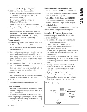
(NEG) terminals on module. 5. Identify a position outside the tank that
5. Run and connect two wires supplied between will indicate LOW and HIGH level. Low
level is the level where treatment starts.
macerator pump and control module. (FIG 9)
Treatment Unit 6. Lightly sand the locations where sensors are
1. Run and connect two wire supplied from control to be located to remove oil and dirt.
module to treatment tank terminal studs. 7. Remove adhesive cover and apply to tank.
Switch Panel Press firmly to remove any air bubbles.
1. Connect cable from switch panel to SPC FIG 9
Tablet Dispenser:
1. Run float cable from Tablet Dispenser to Control
module. Using cable clamp - secure cable on the
wall near dispenser.
2. Connect sensor cable to control module SPC.
Note: Complete programming for Fill and Empty
timing before connecting shutoff valve , key
switch panel or Sensors.
L519 _0919jlc
9