
Page 7 - Raritan Hold-N-Treat for Purasan EX L519v0919
P. 7
LOCATION AND MOUNTING
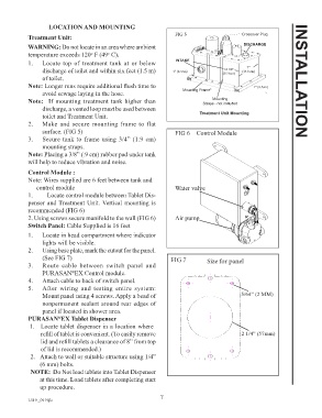
Treatment Unit: FIG 5 Crossover Plug
WARNING: Do not locate in an area where ambient DISCHARGE
temperature exceeds 120 F (49 C).
o
o
1. Locate top of treatment tank at or below INTAKE
7”
discharge of toilet and within six feet (1.5 m) 1” (2.5cm) (35.9cm) (17.8 cm)
14 1/8”
of toilet.
Note: Longer runs require additional flush time to 1” (2.5cm) INSTALLATION
avoid sewage laying in the hose. Mounting Frame*
Mounting
Note: If mounting treatment tank higher than Straps - not included
discharge, a vented loop must be used between
toilet and Treatment Unit. Treatment Unit Mounting
2. Make and secure mounting frame to flat
surface. (FIG 5) FIG 6 Control Module
3. Secure tank to frame using 3/4” (1.9 cm)
mounting straps.
Note: Placing a 3/8” (.9 cm) rubber pad under tank
will help to reduce vibration and noise.
Control Module :
Note: Wires supplied are 6 feet between tank and
control module Water valve
1. Locate control module between Tablet Dis-
penser and Treatment Unit. Vertical mounting is
recommended (FIG 6)
2. Using screws secure manifold to the wall (FIG 6) Air pump
Switch Panel: Cable Supplied is 16 feet
1. Locate in head compartment where indicator
lights will be visible.
2. Using base plate, mark the cutout for the panel.
(See FIG 7) FIG 7 Size for panel
3. Route cable between switch panel and
PURASAN EX Control module.
®
4. Attach cable to back of switch panel.
5. After wiring and testing entire system:
Mount panel using 4 screws. Apply a bead of 5/64” (2 MM)
nonpermanent sealant around rear edges of
panel if located in shower area.
PURASAN EX Tablet Dispenser
®
1. Locate tablet dispenser in a location where
refill of tablet is convenient. (To easily remove 2 1/4” (57mm)
lid and refill tablets a clearance of 8” from top
of lid is recommended.)
2. Attach to wall or suitable structure using 1/4”
(6 mm) bolts.
NOTE: Do Not load tablets into Tablet Dispenser
at this time. Load tablets after completing start
up procedure.
7
L519 _0919jlc